How To Make Stairs In Sketchup
As a carpenter, one of the hardest things to plan is the stairs. Hard math, figuring out the rise and running of each step, and calculating the tread thickness, pitch and finish floor height are all opportunities for mistakes. In this tutorial, you’ll learn how to use SketchUp to plan the deck stairs. Watch the video or continue below.
Stair design pitfalls
Contents
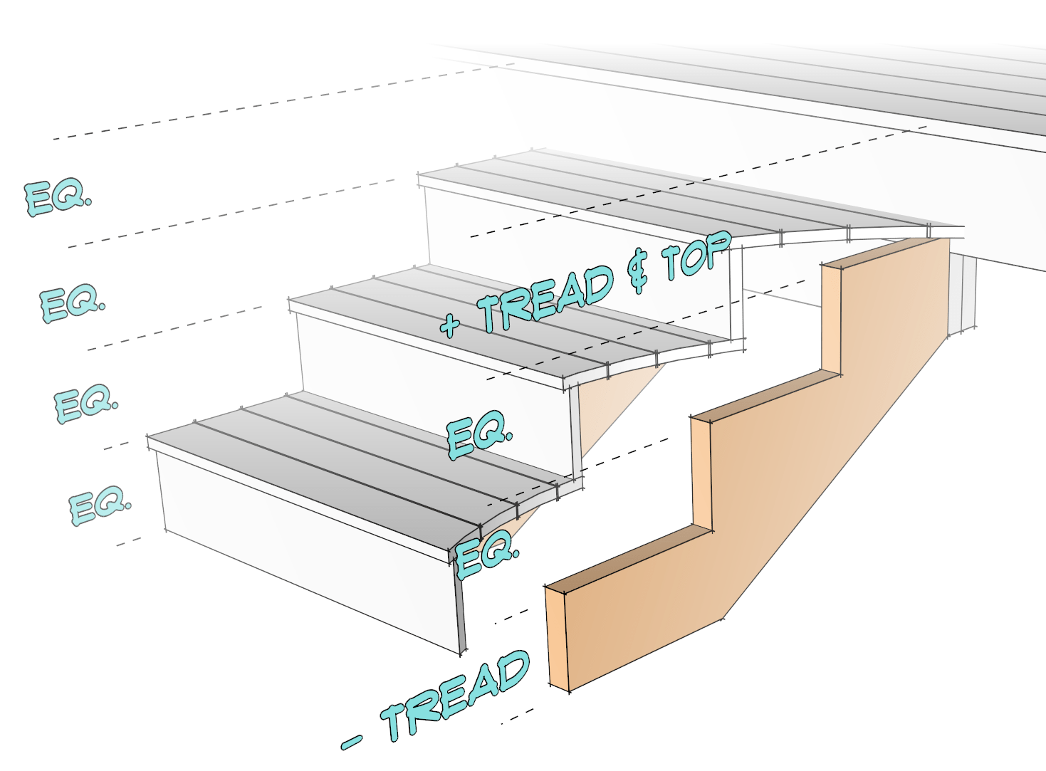
The hardest part about building stairs is knowing how to map out the ropes. The braces are the structural members of the stairs to which the steps and steps are fastened. To build the rope posts, you need to cut out the grooves for the steps and steps, usually from 2×12 pressure-treated lumber.To find out the size of the grooves, you can refer to the ideal building codes and measurements. However, the most common mistake when cutting steel wire is incorrectly calculating the thickness of the steps, steps or the thickness of the finished floor. In the end, you want each ladder to be the same size; From the ground, all the way up to the top of the deck. For this to happen, you need to take into account the thickness of the different materials that you will be installing on the braces. So the tricky part is that the sizes you need to use to cut the lanyard have to do with finishing materials will be installed on top of the chain, not the threaders themselves. So this means you need to be intentional calculate and subtract thickness of the finishing material to reach the chain size.
These are the most common pitfalls when laying strings: (Personal experience)
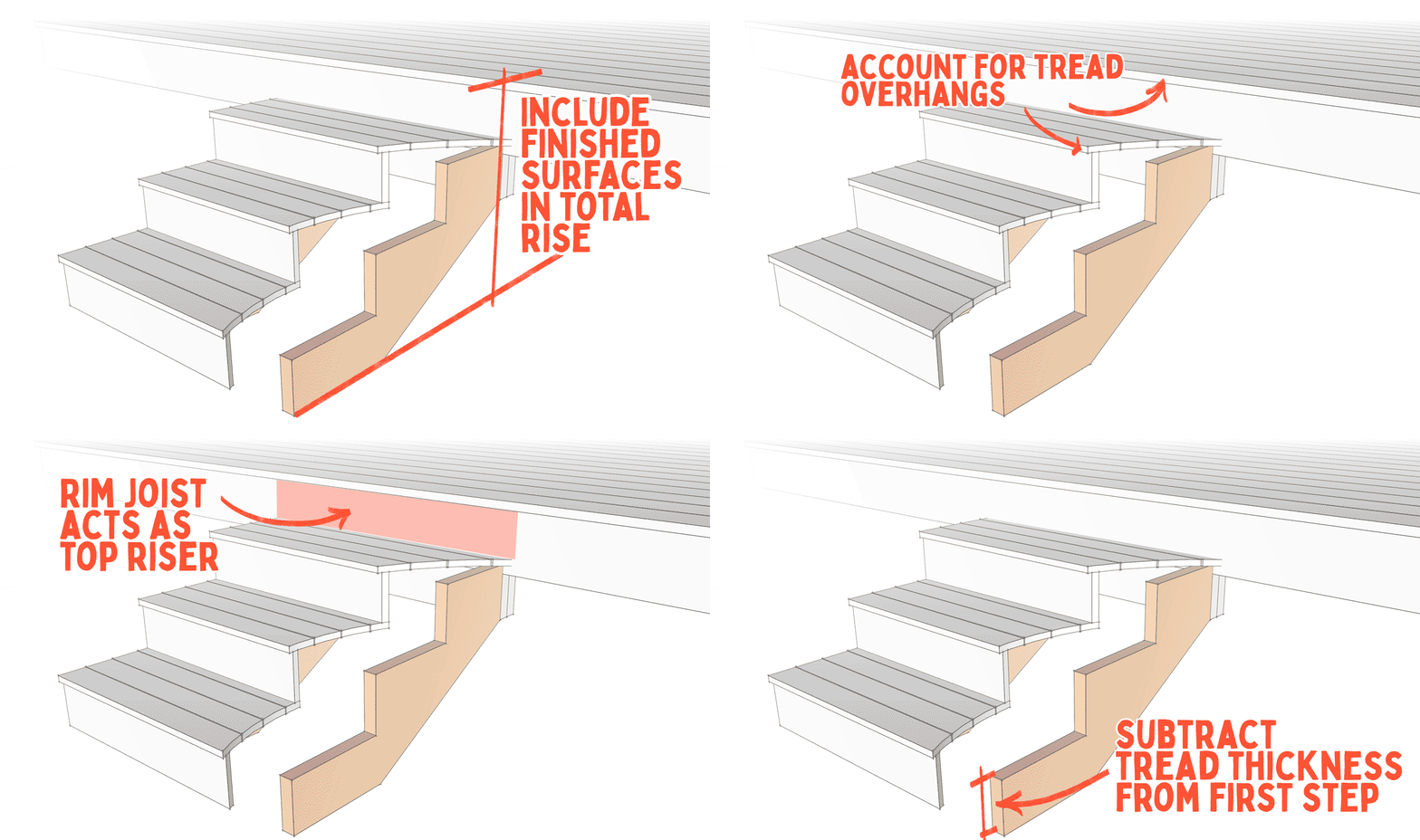
- Total gain is incorrect – The total increase is total vertical distance from the bottom landing to the top of the finished deck at the top of the stairs. A lot of times when you’re planning your sequence, you already have a deck frame ready, but you may not have the deck installed. When measuring the total gain, you need to make sure that you have included the thickness of the flooring material in your measurement. (For interior stairs, you also need to take into account the thickness of the finished floor at the top and bottom of the stairs.)
- Forget about the protrusion – If you are going to overhang an overhang in front of a ladder or rope puller, you need to include that overhang in your calculations so that the overhangs are placed in appropriately.
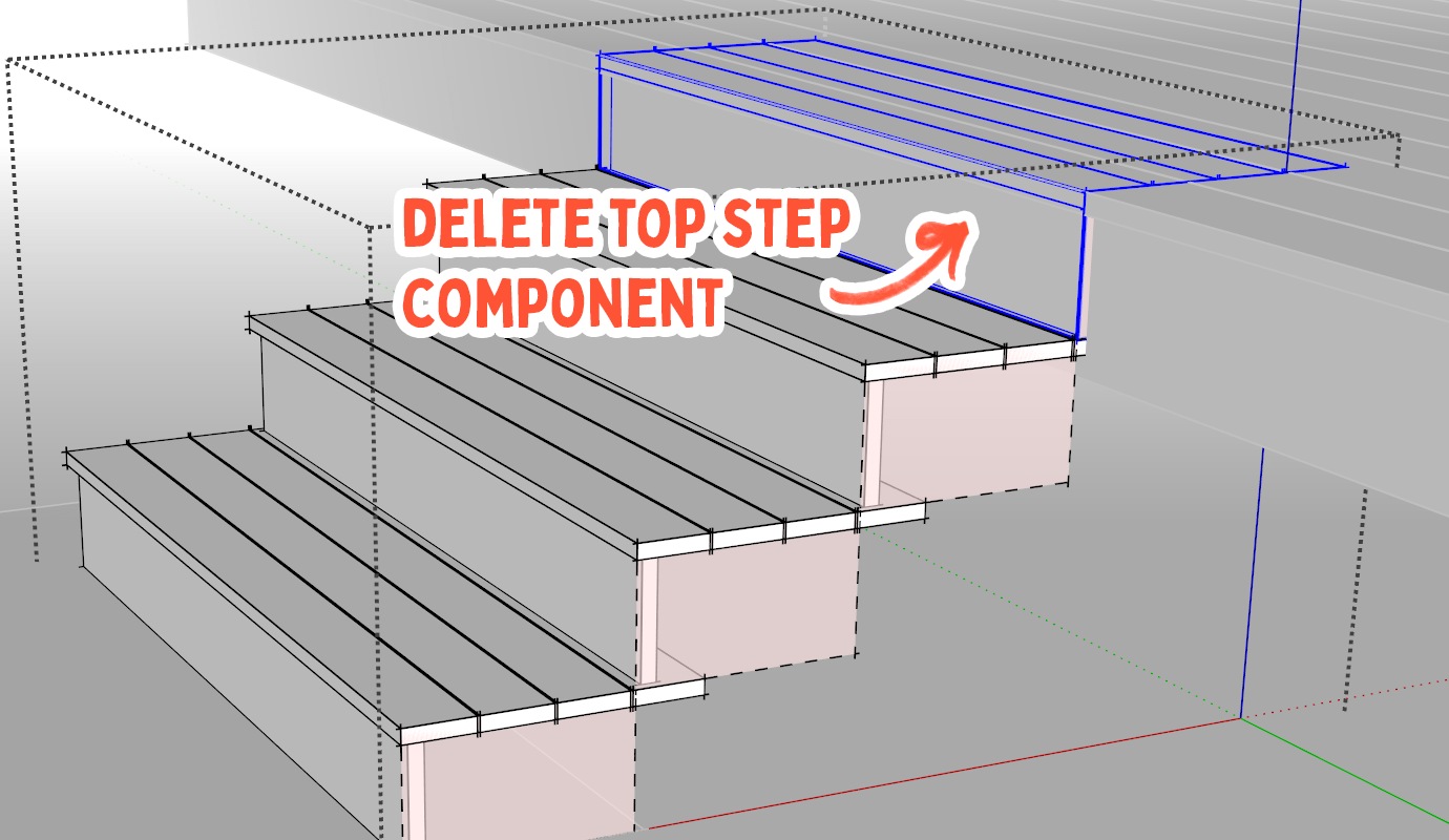
- No lifter at the top step – If you are installing risers on stringers, most of the times you don’t need to install a riser in the top step because the rim joist acts as the top riser. If that is the case, the top step running on the stringer should be one thickness shorter than the riser.
- Height of the bottom step – The height of the bottom overhang must be shorter than all the rest because the rest represents the top surface/finish surface of the tread. After the steps are installed on the slings, the height range of the ladder should be the same for each step, including the ground/landing step up to the first step. This will only happen if the string is shorter for the first step.
Easy sequence planning
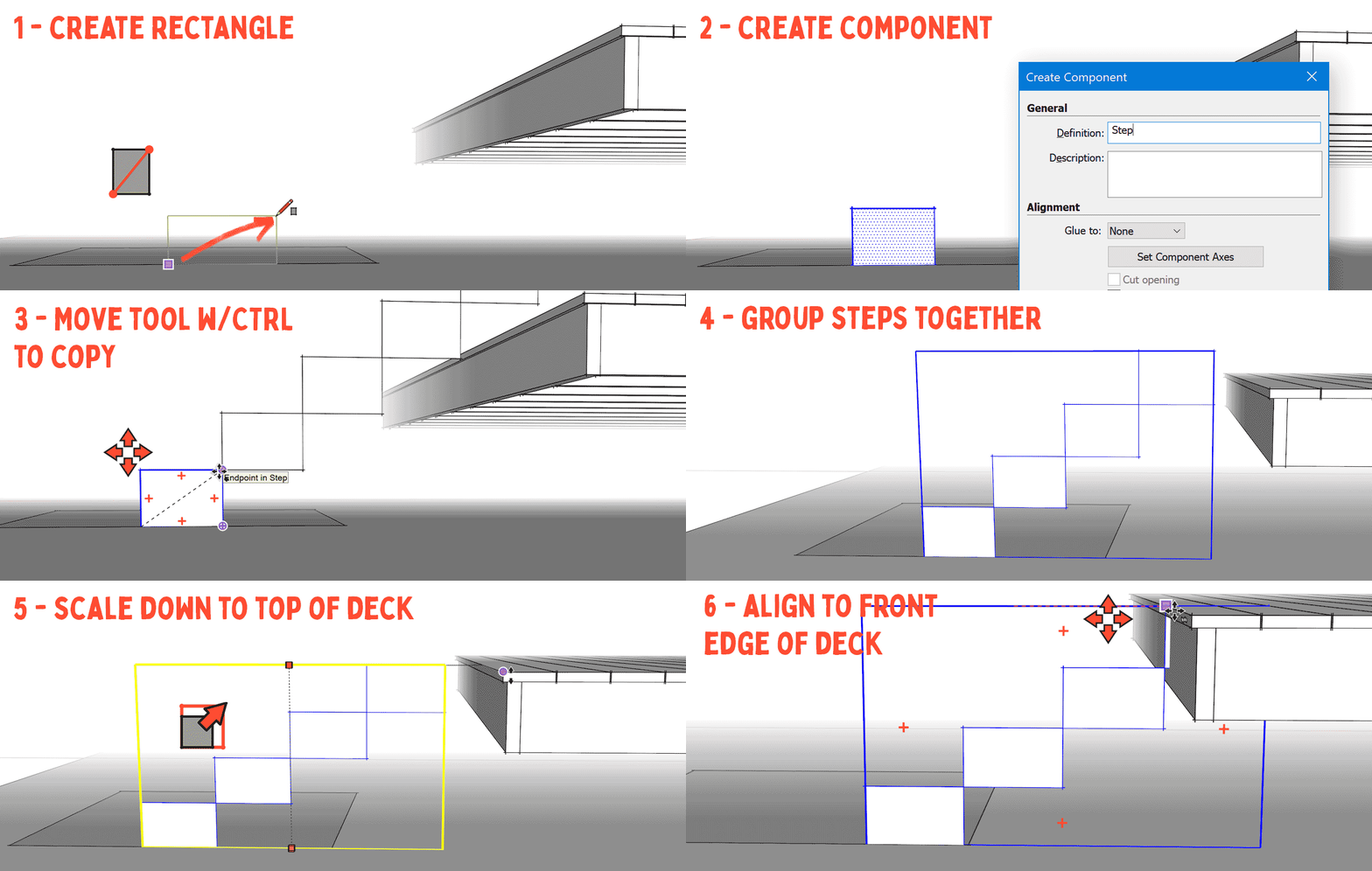
SketchUp makes character sequence planning foolproof. Instead of doing a bunch of mental math, you can create some very simple reference geometries that can be easily scaled to the finished size of the stairs. This will allow you to work backwards until you reach the final wire size. International building codes require a maximum lift height of 7 3/4″ and a minimum tread depth of 10″ for each step. The actual height of the ladder will be determined by the total height of the stairs, divided by the total number of steps. The tread depth offers more flexibility, assuming you don’t have limited space in front of the stairs. When starting to lay out the stairs, you can start with the ideal tread depth or you can adjust the depth of the stairs after you have calculated your step height. Here are some rules of thumb for getting an ideal set of slopes and spikes.
To create a reference geometry for the stairs, follow these steps:
Before you start modeling the stairs, you should have a surface that represents the ground, as well as a geometry that represents the top surface of the deck.
Read more: how to remove the homeless from private property You now have an exact time interval for the height of each step. Instead of measuring the total gain then doing the math to figure out the height of each ladder needed, you can simply use RatioTool S to set the interval automatically for you. Easily! If you want to change the depth of the spikes, you will need to calculate the total number of runs, which is the depth of the spike multiplied by the number of runs. With that number, use RatioTool S to stretch the width of the stairs, then enter the total number of runs and press ENTER. For example, if you want an 11 3/4″ tire and you have 4 tires, type 47 ENTER. (11 3/4 x 4 = 47 )
Build the stairs in reverse
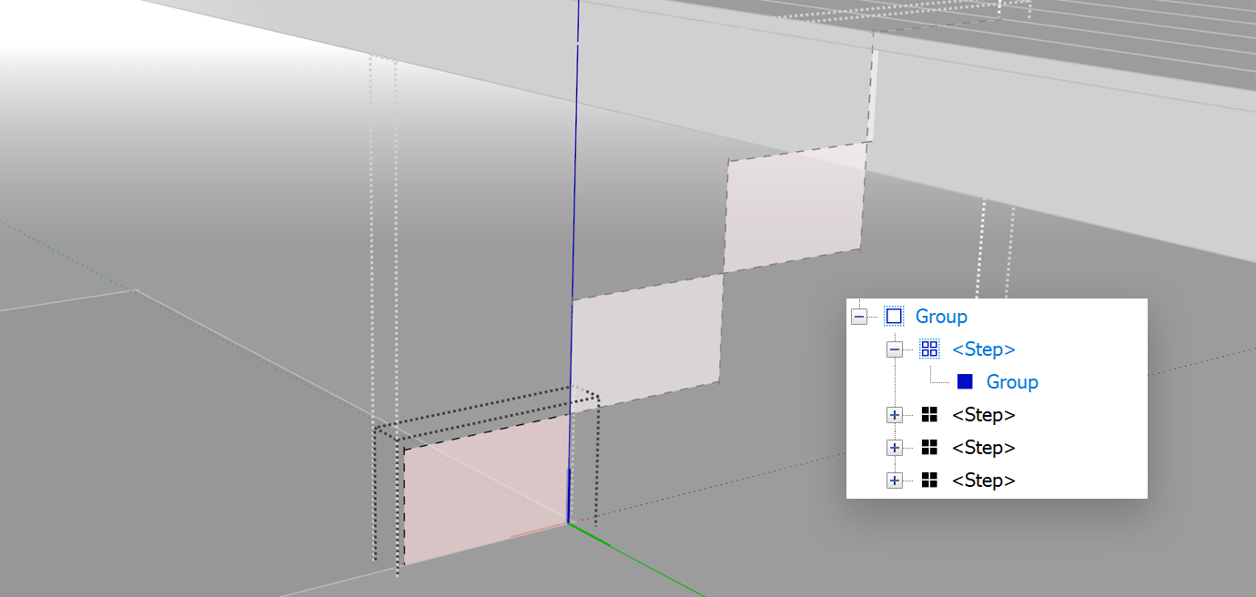
Now that you know the boundaries of where you need the finishing material, you can start building the stairs in reverse, until you get to where you need the column. You should separate the guide lines into their own group before starting to model within the component. You will probably need to create a unique component or two once you have everything in place, but you can keep everything as the same component definition for now.TIP: To make it easier to distinguish reference geometries, you may want to apply semi-transparent material to the faces of the rectangles and assign them to a layer with dashed style.
Treads
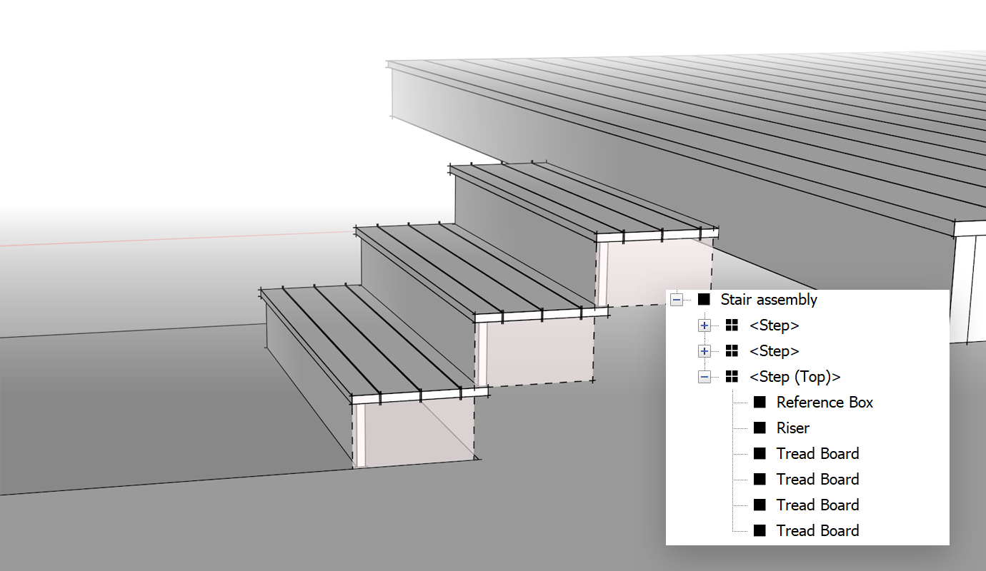
Start by modeling one of the spike boards. You can have a single 2x per track, or you can have several boards that make up each track. Inside the step component, draw a table on the front edge of the step with RectangleR Tool, then extrude it with Push / PullTool P. Stick to the dashed lines for reference. Click three times board, Right click > Create group. Remember, you don’t want to stretch beyond the dashed lines, so extrude downwards to get the thickness of the board. Alternatively, you can decide to use replacement components, but I chose to use groups here as some of these tire boards will need to be customized. It’s up to you if you want to use components and Create uniqueness as needed. MoveM tool with Ctrl/Option modifier to make several copies of the board to stretch the full depth of the tread.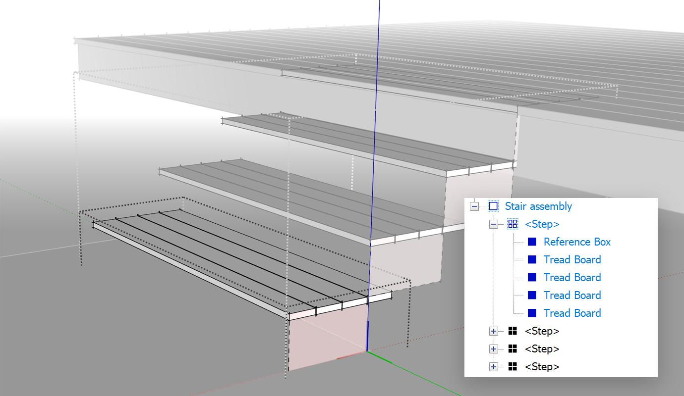
Risk
Read more: How to disable triggers in oracle RectangleR and tools Push / PullTool P, snap to the dashed lines and use the spike board as reference. MoveM Tool to move the ladder back 1/2″. To create overhangs on the sides of the stairs, use Push / PullTool P to shrink 1/2 slant grooves on each side.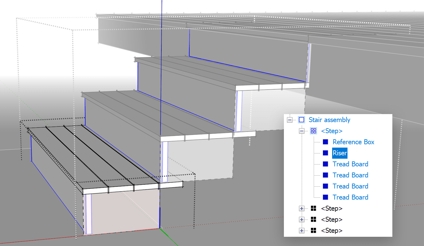
Stringers
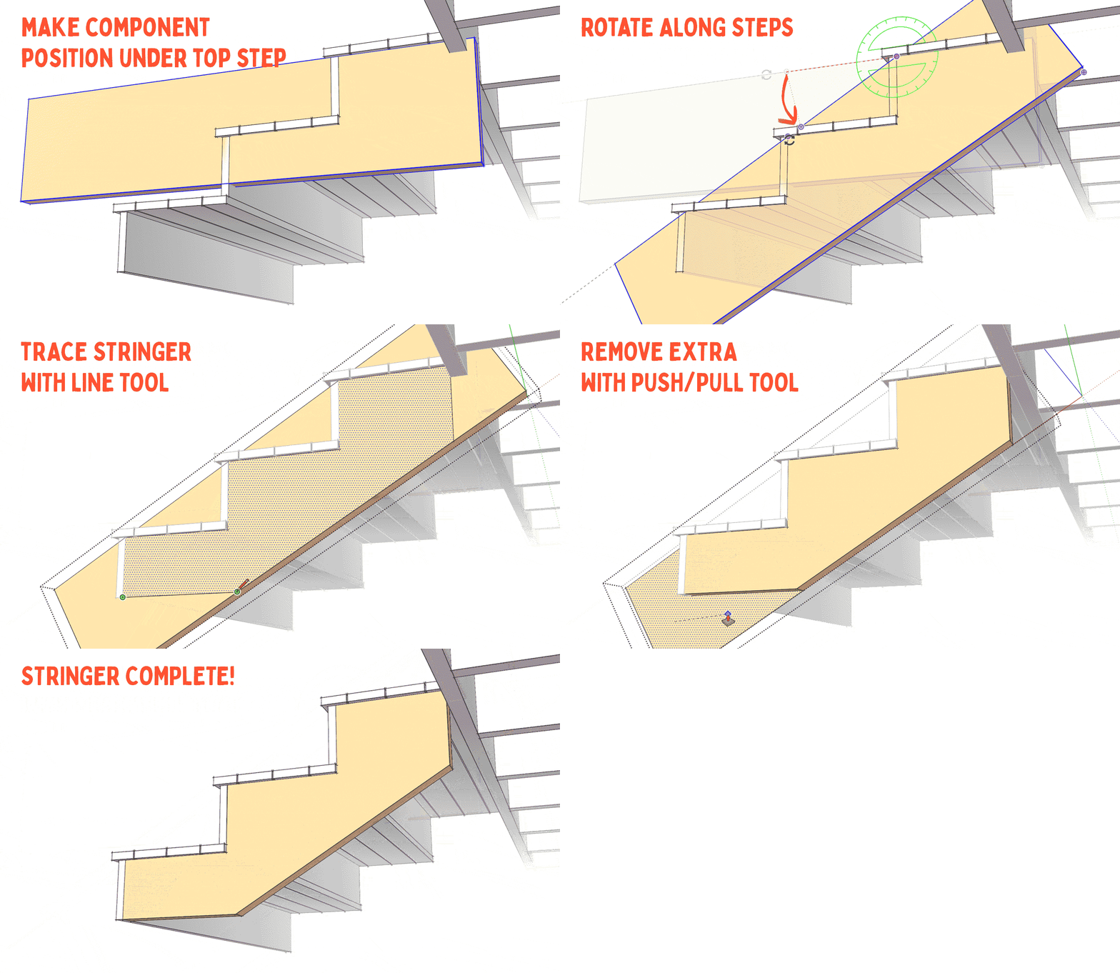
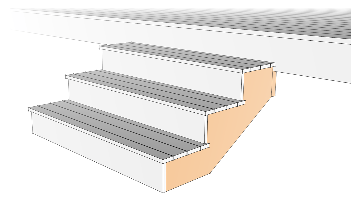
Now that the ladders and ladders are in place, firmly placed on the dashed reference line, we can start modeling the sets of strings. The string set will be created by tracing the edges where the tracks and grooves attach to the stringer.
Last, Wallx.net sent you details about the topic “How To Make Stairs In Sketchup❤️️”.Hope with useful information that the article “How To Make Stairs In Sketchup” It will help readers to be more interested in “How To Make Stairs In Sketchup [ ❤️️❤️️ ]”.
Posts “How To Make Stairs In Sketchup” posted by on 2021-11-03 13:59:37. Thank you for reading the article at wallx.net
