How To Press Button For Two Secinds In Vivado Simulation
On this tutorial, we’ll have the PmodSSD depend seconds.We want a counter which increments each second. We’re going to wish to show the counter worth on the PmodSSD show. We’ll do that in three components: first, we’ll have to know when to increment the counter; second, we have to preserve the counter; and at last we have to feed the depend worth to the show.Reading: How to press button for two secinds in vivado simulationIn our final tutorial, we generated a pulse each millisecond. We will use that very same pulse to allow a counter that may depend to 1000, incrementing each millisecond. That makes a pulse each second for us. Right here’s the code to try this. integer ms_count = 0; reg sec_pulse; all the time @(posedge clk) start sec_pulse <= 0; if (ms_pulse) if (ms_count == 999) start ms_count <= 0; sec_pulse <= 1; finish else ms_count <= ms_count+1; finishWe’ll additionally want to make use of the sec_pulse sign to increment a counter every second. Right here is the code for that. reg [7:0] sec_count = 0; all the time @ (posedge clk) if (sec_pulse) sec_count <= sec_count +1;We will simulate this for a couple of milliseconds. You’ll be capable of see the ms_pulse sign pulse each millisecond. What concerning the sec_pulse sign? We’d have to simulate for a full second to see that pulse, which could take some time. It could additionally burn up lots of disk house once we go to save lots of all the information. A full second is 100,000,000 clock cycles. We actually want a method to by some means brief circuit the millisecond counter whereas we’re simulating. If you happen to’re simulating lengthy counts, like we’re right here, it is a fairly frequent requirement. We’ll introduce a parameter to our prime module.
Dashing Up the Simulation
Contents
You may consider a parameter as a relentless used within the design. The parameter’s worth won’t ever change throughout the simulation of a module. However, completely different situations of a module can have completely different parameter values. First, we’ll introduce a parameter that may maintain the depend worth for counter. The default worth of this parameter is 100,000. With this default worth, the ms_pulse sign will pulse as soon as each millisecond. The parameter is said together with the module, however earlier than the module ports are declared. module prime #( parameter ms_limit = 100000 ) ( enter clk, enter [7:0] change, output reg [7:0] led, output reg [6:0] ssd, output reg ssdcat );Subsequent we’ll change the counter definition to depend as much as ms_limit-1. This received’t change our design’s habits in any respect. all the time @(posedge clk) start ms_pulse <= 0; if (depend == ms_limit-1) start depend <= 0; ms_pulse <= 1; finish else depend <= depend+1; finishOnce we synthesize our design, nothing will change. However, now we modify the occasion of prime in our check bench to override the default worth of ms_limit to simply 100. This can make ms_pulse pulse each 100 clocks within the simulation as a substitute of each 100,000. prime #(.ms_limit(100)) prime ( .clk(clk), .change(change), .led(led) );Rerun your simulation and watch the second counter, which now adjustments each millisecond.Reuse the code to drive the ssd output from the earlier tutorial. wire [3:0] digit; all the time @(posedge clk) case (digit) 0: ssd <= 7’b1111110; 1: ssd <= 7’b0110000; 2: ssd <= 7’b1101101; 3: ssd <= 7’b1111001; 4: ssd <= 7’b0110011; 5: ssd <= 7’b1011011; 6: ssd <= 7’b1011111; 7: ssd <= 7’b1110000; 8: ssd <= 7’b1111111; 9: ssd <= 7’b1110011; 10: ssd <= 7’b1110111; 11: ssd <= 7’b0011111; 12: ssd <= 7’b1001110; 13: ssd <= 7’b0111101; 14: ssd <= 7’b1001111; 15: ssd <= 7’b1000111; endcase assign digit = ssdcat ? sec_count[7:4] : sec_count[3:0];Be certain that to position the code in your prime module such that indicators are declared earlier than they’re used. It’s best to now construct a brand new FPGA and verify that the digits on the show increment each second.All proper, so we’ve simulated our design. However is the output appropriate? It’s not precisely straightforward to verify binary codes for section values within the show that change between digits each millisecond. Let’s write some Verilog code to try this checking for us.
A Mannequin of a Seven-Section Digit
We want a mannequin of the seven section show. We will then put our mannequin into the check bench, and it’ll take the section inputs and substitute that with the numeric worth which the segments symbolize. The mannequin shall be one other Verilog module. The mannequin’s enter would be the section worth and the allow worth. The digit numeric worth would be the output. Let’s begin with the module declaration: module ssd_digit enter allow, enter [6:0] ssd, output reg [3:0] worth );Now, we have to flip the section values again right into a numeric worth. We’ll use a case assertion to do that. all the time @(*) if (allow) case (ssd) 7’b1111110: worth = 0; 7’b0110000: worth = 1; 7’b1101101: worth = 2; 7’b1111001: worth = 3; 7’b0110011: worth = 4; 7’b1011011: worth = 5; 7’b1011111: worth = 6; 7’b1110000: worth = 7; 7’b1111111: worth = 8; 7’b1110011: worth = 9; 7’b1110111: worth = 10; 7’b0011111: worth = 11; 7’b1001110: worth = 12; 7’b0111101: worth = 13; 7’b1001111: worth = 14; 7’b1000111: worth = 15; endcaseThat is simply the inverse of the desk in our prime.v file. It takes the section values and turns them again right into a numeric worth. However, we’ve acquired a pair points. First, there are actually two completely different values for the digit “C”. To unravel this, we’ll use two completely different parameters: an uppercase “C” and a lowercase “c”. To deal with each circumstances, we’ll want so as to add one other entry in our desk. 7’b0011001: worth = 12;There’s one other difficulty: what if not one of the section values match a desk entry? Let’s use a default worth on this case. default: worth = ‘bx;This entry within the case assertion will trigger the worth sign to be set to X (unknown) if not one of the different entries match segments. The default assertion ought to come simply earlier than the endcase assertion.
Instantiating the Mannequin within the Check Bench
We want two digits in our check bench, in addition to eight wires to hook as much as the output of our digit fashions. Additionally, we’re going to wish an allow sign for every digit. The allow shall be our ssdcat sign. We all know from earlier than that the low digit is lively when ssdcat is low and when ssdcat is excessive, the excessive digit is lively. Right here is the code. wire [7:0] digits; ssd_digit PmodSSD0 ( .allow(~ssdcat), .ssd(ssd), .worth(digits[3:0]) ); ssd_digit PmodSSD1 ( .allow(ssdcat), .ssd(ssd), .worth(digits[7:4]) );The whole lot appears to be like good from right here. We will construct an FPGA and watch the seconds tick by (in hex, after all). Working a simulation and looking out on the output worth, we see the simulation counts appropriately. What else do we have to do? Within the Actual World®, this won’t be sufficient. What if our check might verify itself? What would the advantage of that be? Properly, if in case you have a self-checking check, you then have an automatic check you’ll be able to run at any time when your code adjustments. If it passes the check, you’ll know your code works. You don’t need to construct an FPGA and watch the outcomes, and also you don’t have to look at a check waveform to know whether or not the code works. Implementing a self-checking check saves an amazing quantity of labor and unpredictability: one thing that’s effectively value doing.Read more: How to play with friends on super mario runIn our case right here, we have to depend the seconds outdoors of our FPGA. Ideally, you’ll write one thing referred to as a “behavioral model”. A behavioral mannequin if a Verilog mannequin of your design, which behaves the way you need your FPGA to, however with much less complexity. Your check bench simply runs your FPGA and the mannequin and checks to see that the FPGA outputs match these of the mannequin. Let’s create a mannequin of our second counter.
Second Counter Mannequin
The mannequin wants as enter the clock sign, and it ought to output an eight-bit worth which counts the seconds. Additionally, keep in mind that we short-circuited the millisecond counter to make the simulations run quicker. I write the mannequin with the identical parameter because the precise design and override it from the check bench. That retains the information of how the parameter is overridden to the check bench solely. A very good rule of thumb is to maintain information as native as potential. `timescale 1ns/1ns module mannequin #( parameter ms_limit = 100000 ) ( enter clk, output [7:0] seconds ); integer counter = 0; all the time @(posedge clk) counter <= counter+1; assign seconds = counter / (ms_limit * 1000); endmoduleThat’s your entire mannequin. It’s fairly straightforward to inform it’ll depend the seconds correctly, and it’s a lot less complicated than our RTL design. Now, we’re simply instantiating the mannequin in our check bench, like this: wire [7:0] model_seconds; mannequin #(.ms_limit(100)) mannequin ( .clk(clk), .seconds(model_seconds) );Bear in mind, we have to override the ms_limit parameter within the mannequin occasion.
Evaluating Outcomes
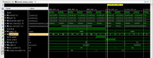
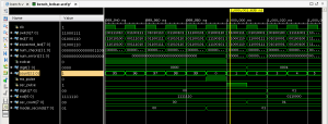
Now, we simply have to match the outcomes popping out of the ssd_digit modules with what comes out of our behavioral mannequin. One thing like this: all the time @(posedge clk) start num_checks = num_checks+1; if (digits != model_seconds) start $show(“ERROR: digits value %0x does not match expected value %0x at time %0fns”, digits,model_seconds,$realtime); num_errors = num_errors+1; finish finishWord that the incrementing of num_checks and num_errors will not be being accomplished with a nonblocking project. Bear in mind, it is a check bench and never RTL. There may be a further verify each clock edge being accomplished on the LED outputs, and we wish each checks to depend. If we used a nonblocking assign,x we’d solely depend one verify every clock cycle and will masks errors relying on which all the time block runs first.Additionally, I’ve modified the check bench to attend for 20 seconds (or milliseconds since we brief circuit the simulation) after which cease. So I’ve changed the repeat assertion used to attend to complete the simulation with a Verilog wait assertion. Like this. preliminary start wait (model_seconds == 20); $show(“Simulation complete at time %0fns.”,$realtime); if (num_errors > 0) $show(“*** Simulation FAILED %0d/%0d”,num_errors,num_checks); else $show(“*** Simulation PASSED %0d/%0d”,num_errors,num_checks); $end; finishNow we simply run the simulation and see the way it works. run all ERROR: digits worth 0 doesn’t match anticipated worth 1 at time 1000000.000000ns ERROR: digits worth 0 doesn’t match anticipated worth 1 at time 1000010.000000ns ERROR: digits worth 0 doesn’t match anticipated worth 1 at time 1000020.000000ns ERROR: digits worth 11 doesn’t match anticipated worth 1 at time 1001010.000000ns ERROR: digits worth 0 doesn’t match anticipated worth 1 at time 1002010.000000ns ERROR: digits worth 11 doesn’t match anticipated worth 1 at time 1003010.000000ns ERROR: digits worth 0 doesn’t match anticipated worth 1 at time 1004010.000000ns ERROR: digits worth 11 doesn’t match anticipated worth 1 at time 1005010.000000nsThat is adopted by numerous error messages and at last wraps up with ERROR: digits worth 33 doesn’t match anticipated worth 13 at time 19995010.000000ns ERROR: digits worth 11 doesn’t match anticipated worth 13 at time 19996010.000000ns ERROR: digits worth 33 doesn’t match anticipated worth 13 at time 19997010.000000ns ERROR: digits worth 11 doesn’t match anticipated worth 13 at time 19998010.000000ns ERROR: digits worth 33 doesn’t match anticipated worth 13 at time 19999010.000000ns Simulation full at time 19999990.000000ns. *** Simulation FAILED 18136/4000000 $end referred to as at time : 19999990 ns : File “/home/pete/tutorial6/tutorial6.srcs/sim_1/new/bench.v” Line 85What has gone unsuitable? Clearly with 18136 failures out of 4000000 comparisons issues are largely appropriate. Let’s take a look at the waveform from the simulation at time 1,000,000ns. Actually zoom in to that point so that you solely see 10 or so clock cycles. Here’s what my simulation is exhibiting me.Properly, I can see why sec_count doesn’t match model_seconds. The timing is off by a couple of clock cycles. This is because of some latency within the design. We will appropriate for this in plenty of methods. We will cut back the latency within the design, or we will add latency to the mannequin. Or each. One factor I discover is that the ms_pulse and sec_pulse indicators will not be coincident. This can be OK, however we might cut back the latency some by bringing in sec_pulse by one clock cycle. This additionally makes the design a bit of bit cleaner and in a posh design would possibly assist preserve issues easy.Let’s look once more on the code which generates ms_pulse. integer depend = 0; reg ms_pulse = 0; all the time @(posedge clk) start ms_pulse <= 0; if (depend == ms_limit-1) start depend <= 0; ms_pulse <= 1; finish else depend <= depend+1; finishDiscover how ms_pulse is positioned in a flip-flop? Additionally, discover how it’s excessive when the depend worth is zero. Let’s change the definition of ms_pulse to be combinational. This can eradicate the delay of 1 clock.The outcome appears to be like like this. integer depend = 0; wire ms_pulse = depend == ms_limit-1; all the time @(posedge clk) if (ms_pulse) depend <= 0; else depend <= depend+1;Hey, that’s even less complicated to code. Let’s run our simulation and see if we now have modified issues.


Monitoring extra bugs
It appears to be like like we nonetheless have some errors although. Right here is the subsequent error message. ERROR: digits worth 11 doesn’t match anticipated worth 1 at time 1001000.000000nsLet’s zoom in on that point and see what’s occurring.

- prime.v
- bench.v
- ssd_digit.v
- mannequin.v
Last, Wallx.net sent you details about the topic “How To Press Button For Two Secinds In Vivado Simulation❤️️”.Hope with useful information that the article “How To Press Button For Two Secinds In Vivado Simulation” It will help readers to be more interested in “How To Press Button For Two Secinds In Vivado Simulation [ ❤️️❤️️ ]”.
Posts “How To Press Button For Two Secinds In Vivado Simulation” posted by on 2022-04-09 18:54:05. Thank you for reading the article at wallx.net


