What is xc in rlc circuit
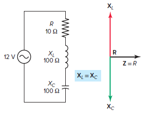
What is video xc in rlc circuit Circuits in which induced reactance equals capacitive reactance (XL = XC) is called resonant circuit. They are usually collector circuits or parallel circuits and both RLC or LC Process. The impedance vector of a typical assembled RLC resonant circuit is demonstrated in Determination 1 and is summarized as follows:
- XL and XC are 180 levels of part.
- XL and XC have equal value (100 Ω), then have web resistance of 0 ohm.
- One opposite of current is R (10 Ω).
- Z equals R and equals minimum value, allowing the best quantity present to be in circulation.
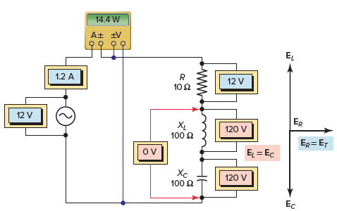
Read: what is xc in rlc circuitDetermine 1 Impedance vector for receiver RLC resonant circuit. The voltage vector for the RLC resonant circuit obtained is demonstrated in Determination 2 and is summarized as follows:
- Current as decided by Ohm’s Law To be
- The same amount of current in the way of all parts.
- The voltage drop across the inductor is
- The voltage drop across the entire capacitor is
- The XL and XC through-through voltages are equal (120 V) and 180 levels are partially offset so that any voltage rejects the opposite.
- As a result of each inductor and capacitor being removed, one current limiting element will be the resistor and the supply voltage is fully utilized seemingly throughout the resistor.
- Afterward, part corner between circuit current and supply voltage will probably be zero and the base problem will probably be 1, or a hundred computers.
- The circuit can be considered as purely resistive essentially with the inductor’s inductive response VARs being eliminated by the capacitor’s inductive capacitance VARs. Real energy is
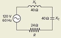
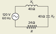
Determine 2 Voltage vector for the receiver RLC resonant circuit.Calculation sequence of RLC resonant circuit Case 1For the RLC resonant circuit collection demonstrated in Define 3decision:
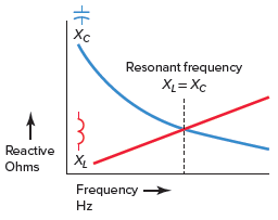
Determine 3 Example: circuit 1.Resolution:[text{a}text{. Z=R=24 }!!Omega!!text{ }][text{b}text{. I=}frac{{{text{E}}_{text{T}}}}{text{R}}text{=}frac{text{120V}}{text{24 }!!Omega!!text{ }}text{=5A}][begin{align}& text{c}text{. }{{text{E}}_{text{R}}}text{=I }!!times!!text{ R=5A }!!times!!text{ 24 }!!Omega!!text{ =120V} & {{text{E}}_{text{L}}}text{=I }!!times!!text{ }{{text{X}}_{text{L}}}text{=5A }!!times!!text{ 40 }!!Omega!!text{ =200V} & {{text{E}}_{text{C}}}text{=I }!!times!!text{ }{{text{X}}_{text{C}}}text{=5A }!!times!!text{ 40 }!!Omega!!text{ =200V} end{align}][begin{matrix} Apparenttext{ }Power & ={{E}_{T}}~times ~I & =120V~times ~5A=600VA Truetext{ }Power & ={{E}_{R}}~times ~I & =120V~times ~5A=600W Nettext{ }Reactivetext{ }Power & =left( Itimes {{E}_{L}} right)-left( Itimes {{E}_{C}} right) & =0VARs end{matrix}][text{e}text{. Power Factor=}frac{text{W}}{text{VA}}text{=}frac{text{600W}}{text{600VA}}text{=1}]Recall that the induced reactance is different right away because the frequency of the AC supply voltage (XL = 2πfL), while the capacitive resistance varies opposite because of the frequency (XC = 1/2πfC). When an inductor and a capacitor are related in a circuit, there is a possibility that a resonant frequency where the inductive reactance and the capacitive reactance will be equal. The rationale for this is that as frequency increases, the induced reactance increases and the reactance decreases. The next system is used to find the resonant frequency when the values of inductance and capacitance are recognized:
- The frequencies are classified and the current values of completely different frequencies are plotted on the graph.
- The magnitude of the current is an operation of frequency.
- The response curve starts close to zero, reaches its maximum value above the resonant frequency, then drops to close to zero as the frequency turns into infinity.
- There is a small frequency difference, called the resonant band or moving band, about both aspects of resonance where current is roughly the same because it is in resonance.
- The circuit can be used to isolate or filter output a certain frequency.
Determine 6 Frequency response curve for receiver RLC resonant circuit In receiver RLC circuit at resonance, the two reactances XL and XC are equal and cancel. In addition, the 2 voltages representing VL and VC are also opposite and equal in value, thus canceling each other out. 7 Compare the case where the circuit exists above or below resonance with when the circuit is in resonance and is summarized as follows:
- When operating above its resonant frequency, the receiver RLC circuit has the dominant characteristics of the receiver RL circuit.
- When working below its resonant frequency, the receiver RLC circuit has the dominant characteristics of the receiver RC circuit.
- When working at its resonant frequency:
- – Reaction (X) is zero because XL = XC.
- – Impedance is minimum and current is maximum when Z = R.
- – The measured potential across the two receiver reactants L and C is zero.
- – All supply voltage is dropped across the entire resistor.
- – The part angle between the supply voltage and current is zero and the facility problem is 1.
Determine 7 Characteristic of the RLC resonant circuit connected in series.Rate the question
Read more: What does poop taste like?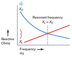
(b) Zero, because the voltages EC and EL have the same value and cancel each other out. (c) Induction due to XL will develop better than XC. (d) The capacitance as a result of the XC will grow to be better than the XL. (E) Impedance will increase and current will be lower as there will probably be some resistance other than resistor limiting current circulation. (F) Impedance will increase and current will be lower since there will likely be some resistance beyond resistance limiting current circulation. Vary the frequency of the supply base to current and voltage across the resistor at maximum value. This is the resonant frequency.9. The transparent voltages XL and XC are equal and 180 degrees out of phase with each other then in a circuit that is purely resistive in nature with the inductor’s induced reactive VARs being rejected by the capacitor’s induced capacitive VARs .ten. Receiver resonant circuits can be used to select a specific frequency in the communication circuit or to generate a voltage greater than the supply voltage.11. 300 volts Read more: What is the net worth of scott cawthon
Last, Wallx.net sent you details about the topic “What is xc in rlc circuit❤️️”.Hope with useful information that the article “What is xc in rlc circuit” It will help readers to be more interested in “What is xc in rlc circuit [ ❤️️❤️️ ]”.
Posts “What is xc in rlc circuit” posted by on 2022-05-04 23:18:44. Thank you for reading the article at wallx.net
